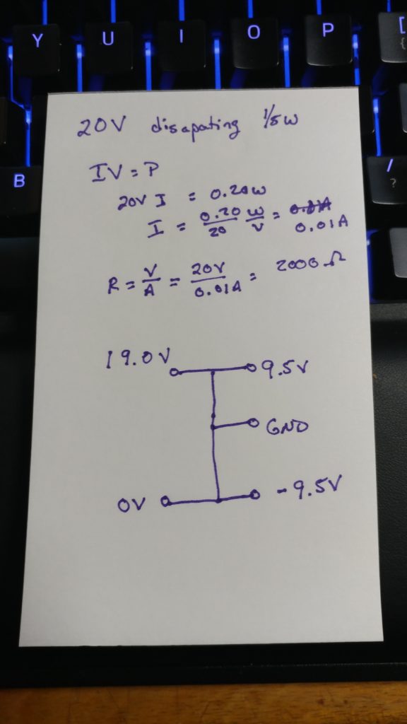
Note: A couple of paragraphs on the power supply have been struck out due to a basic electronics error I made.
A lot of my projects suffer from analysis paralysis. In search of the perfect, I forget to actually build something. Forget is a cop-out. I am afraid to build something. Something better would result if I waited just one more day and read one more article.
My modular project was well on the way to this. I mean, I have at least six different oscillator schematics. At the rate I was going, I’d never pick one and order the parts. Then I saw this video by cosmic garden.
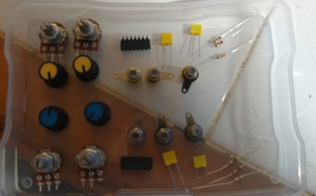
That got me thinking, I could build almost everything in that video with items I had on hand. The only limitation was I did not have enough 100K potentiometers for the Baby 8 sequencer. I might not have exact resister or capacitor values, although I doubt that, but even if I don’t have the right ones you can get close. A quick order to Amazon could solve the potentiometer problem. Thus was the “Atari Punk Modular” born.
There are two other things I’m lacking for making a Eurorack version. I don’t have 3.5mm audio jacks. I don’t have 1/4″ audio jacks for that matter. I also don’t have the ribbon cables and rectangular connectors for connecting the power supply to the modules. For that matter, I don’t have a power supply period.
What I do have is a box of banana jacks and banana plugs to make the corresponding cables. They were appropriately bought for a never-completed project to build an old ATX power supply into a bench power supply for electronics. I could use the banana jacks for the signals on my simple modular. I could build the bench power supply for the modular. A quick Amazon order got me 40 100K potentiometers which were delivered last night. I’m ready to start.
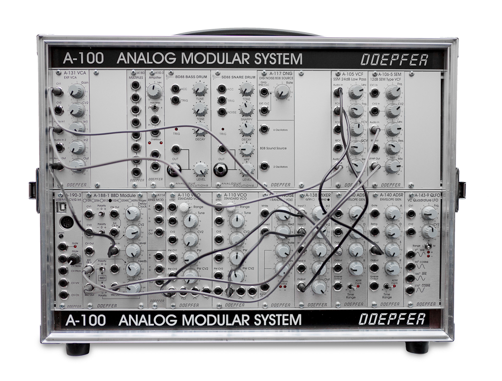
One change will be in the form factor. Because they won’t be Eurorack compatible modules in either signal connectors or the power connectors why bother fitting them into that format. While researching banana jack formats I came across the Loudest Warning 4U format via Slightly Nasty. I’m going to use that for the front panels. He recommends Eurorack style power. For now, I’ll get something running and worry about converting power supplies later.
While I’m on the topic of power supplies, I don’t really like the idea of having the system tied to a bench supply. While I have no problem using an external supply that connects via banana jacks, for now, I’d like something more portable. The problem is finding a portable power supply is the need for negative voltage supplies for some components. I could go with batteries, but I prefer being able to plug into the wall. I remembered I have a power supply, rated at 19 volts and a bit over 2 amps, for a long-gone Netbook.

The Atari Punk Console is usually run on a 9-volt battery. A two resistor voltage divider would give me a 9-volt output from its center. That would be the straightforward answer, but would not supply the negative voltage. The solution to that is to take a 9.5 volt supply off the positive side of the power supply. I would still use a voltage divider, but instead of making the ground of my external circuits the ground of the center of the voltage divider. I could then connect my external components requiring negative power to the ground of the adaptor. Because they would be in circuits whose ground was the center of the voltage divider they would see a -9.5 volt potential..
All the resisters I have are 1/4
Okay, all of that has a gross conceptual error. Adding loads across the resisters in the voltage divider would create parallel resistance and thus mess up the calculations. I might be able to make this work with either 78xx/79xx or 317/337 voltage regulators, but only at a max of 6 volts and -6 volts. Even then I’d need to read the datasheets. I think I need to go to my plan B for the power supply which I’ll cover in a different post.

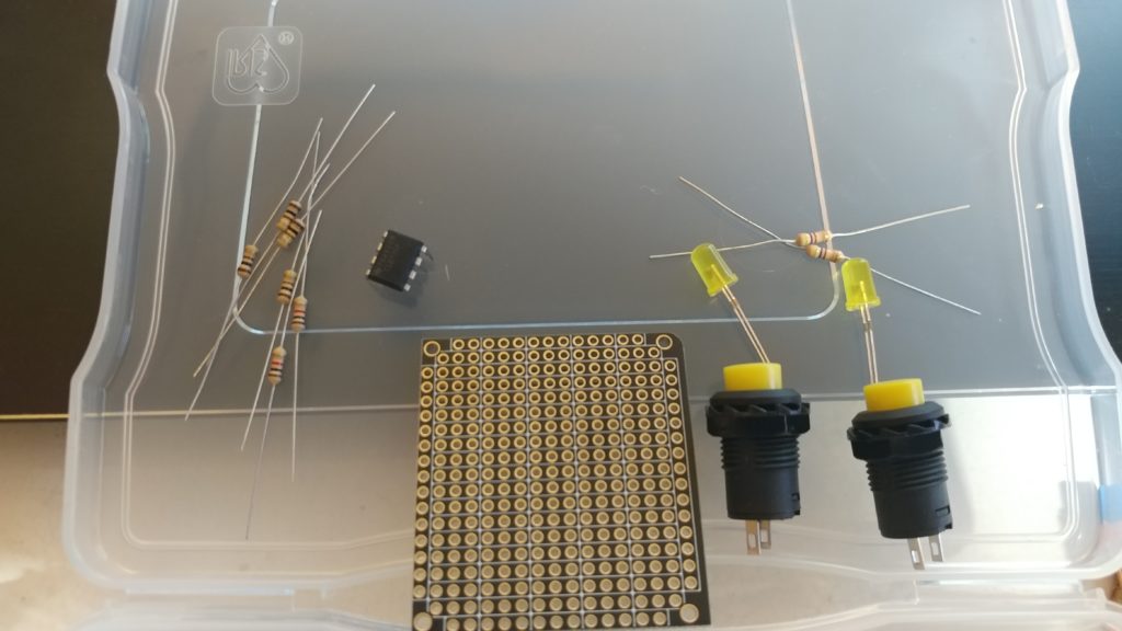
For the first module, I will make a pair of Atari Punk Console oscillators. A single one is present in the video, but I like the idea of having a pair. As I said, outside of potentiometers I have everything I need. The Atari Punk Console is a minor evolution of a circuit by the great Forest Mims. He first introduced it in the Radio Shack booklet Engineer’s Notebook: Integrated Circuit Applications back in 1980((It is in his currently available Engineer’s Mini-Notebooks Volume I: Timer, Op Amp, and Optoelectronic Circuits & Projects)). Nearly any website you find concerning synth DIY brings it up at some point. It is a commonly recommended first circuit for new synth builders. It uses two 555 timer chips or one 556, which is two 555 chips in one package. Beyond that, it only requires two potentiometers, two capacitors, and three resisters.

I will be adding two features to the common circuit. First, pin 6 of 555, which always an external voltage to change reference voltages inside the chip, thus changing the frequency of the oscillator. I’ll add four inputs, one for each of the four chips in my dual oscillator. This will not make the circuit tunable to 1 volt per octave voltage control. While it is possible to build a 555 timer-based oscillator that allows tuning, this Thomas Henry circuit, for example, the Atari Punk Console is not one of them. Also, the 555 chips I have on hand are not well suited to that precise control. The second feature I will add is a buffer to the audio output of both oscillators. This will be a simple TL072 dual op-amp chip. Each oscillator will use one op-amp and a 100-ohm resistor on the output to buffer them.

Finally, I want to experiment with one possibility. What if I feed the output of one oscillator into either control voltage input of the other? I’m going to experiment with this on the breadboard first. If there are useful or interesting results, I’ll add a pair of pushbuttons to take the audio of one oscillator into either or both. If I add that feature, I’ll run it and the external control voltage through an op-amp configured as a volt adder. How will that sound? Who knows, but that’s the fun of something like the APC. All the components cost less than $3 and half of that is the potentiometer. If it works, it would be the APC equivalent of a complex oscillator from a West Coast synth. In that case, I’ll call it the Atari Goth Console, because what is a goth if not a complex punk.
As I have all the parts, I’ll start working on this tonight. I should have the power supply, at least, for tomorrow’s post. With some effort, I can have some sound from the dual APC as well.


[…] The Atari Punk Modular 2021-03-04 […]